Project Navigator for IEC Editors
See also: IEC 61131 Language Editor Programming
See also: Enhanced IEC 61131 Guide
Topic Menu
IEC Language Editors
There are five IEC languages available:
Recommended for backwards-compatibility of existing code only: While all products support the IEC languages, some products optionally allow the use of Enhanced IEC functionality as a licensed feature. The use of this editor is automatic if the licensing is in place and the option to allow it is selected. See also: Enhanced IEC 61131 Guide
Project Navigator Overview 
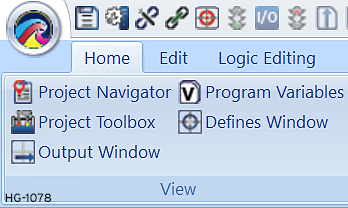
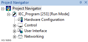
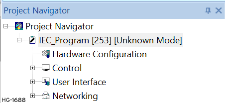
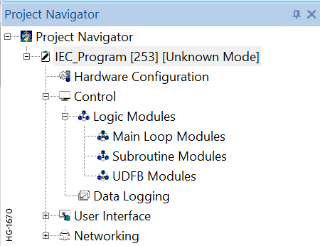
To access the Project Navigator select Home>View>Project Navigator.
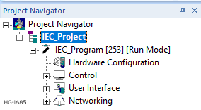
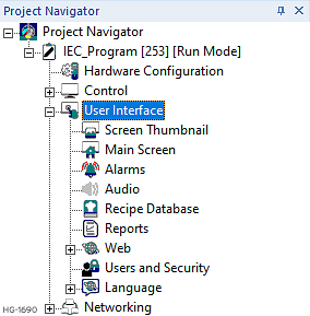
The Project Navigator will open:
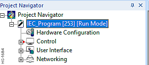
The PROJECT is a centralized location or container for the information about and concerned with an entire installation. When a project is opened, all necessary information is made available. Using Project Navigator can include multiple projects supporting several networks and controllers can be easily designed, maintaining the interconnections and dependencies in an easy-to-use, logical manner. The Project Navigator is a key tool to the management of a project. The Navigator presents all information in a logical hierarchical format such that any information can be accessed easily. It also facilitates navigation between different programs within a project or out of project. Programs must be assigned a unique Network ID![]() Usually refers to the ID of the device on a supported CAN, such as CsCAN, CANopen, etc. Each device must have a unique network ID. Also called Node ID. in a project. The network ID is shown next to the program name in brackets along with the mode. Unsaved projects and programs are indicated by ’*’ next to the name.
Usually refers to the ID of the device on a supported CAN, such as CsCAN, CANopen, etc. Each device must have a unique network ID. Also called Node ID. in a project. The network ID is shown next to the program name in brackets along with the mode. Unsaved projects and programs are indicated by ’*’ next to the name.
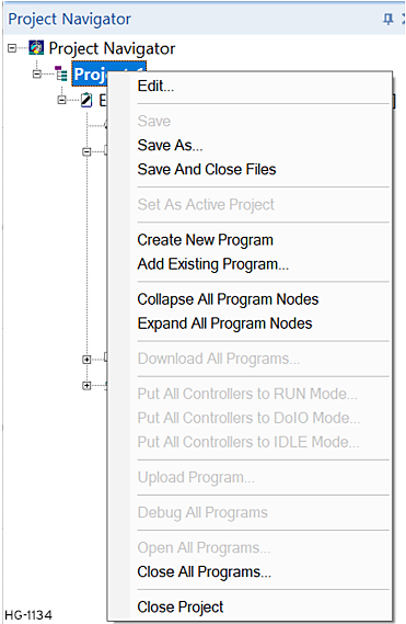
Project Navigator - Right-Click Options
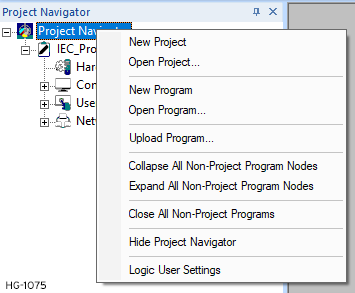
Most functions of Project Navigator can be performed by right-clicking on the related node and then selecting the desired functionality from the pop-up menu shown.
Return to the Top: Project Navigator for IEC Editors
Create New or Open Program or Project
New Project - Creates a new project (* .cpj)
Open Project - Opens an existing project. Right-click on this option and select the project to be opened.
New Program - Creates a new Stand-Alone program (*.CSP). By right-clicking this option untitledx.CSP Stand-Alone program will be created with unknown ID and Mode at the Project Navigator node level in navigator. See User Settings for IEC User Settings for Advanced Ladder Overviewfor more details. Select IEC 61131 Language Editors.
Open Program - Opens an existing program (*.CSP) as a Stand-Alone program. An Open File dialog will be shown for browsing and selecting the program to be opened.
Upload Program
See also: Upload a Program from a Controller
Selecting this option will open a dialog box asking to enter the network ID of the device from where the program is to be uploaded. On providing valid Network ID, the program will be uploaded and added as a stand-alone program in the Project Navigator.
Collapsing or Closing a Program
Collapse All Non-Project Program Nodes - Collapses all stand-alone programs (*.CSP) expanded currently in the Project Navigator.
Expand All Non-Project Program Nodes - Expands all stand-alone programs (*.CSP) collapsed currently in the Project Navigator.
Close All Non-Project Programs - Closes All Stand-Alone programs (*.CSP) opened currently in the application.
Hide Project Navigator - Hides the Project Navigator
Logic User Settings - Opens the User Settings for IEC .
User Settings
Opens the User Settings for IEC
Return to the Top: Project Navigator for IEC Editors
Project Node for IEC
Project Node - Right-Click
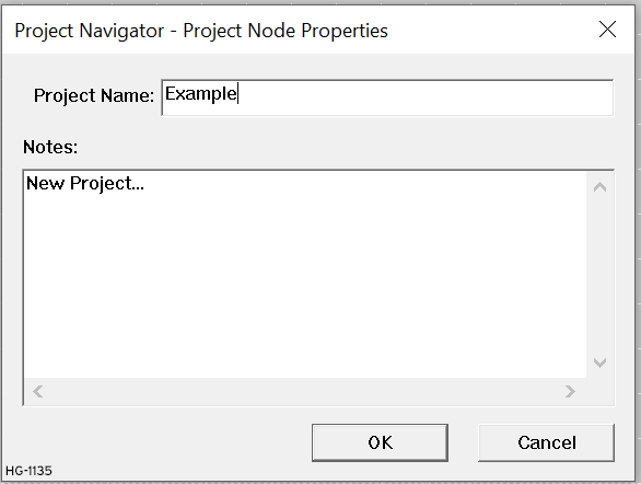
In the Project Node Properties dialog, a project can be renamed, and notes can be inserted about the project –Author, number of controllers, network type, etc. Click OK after completion.
Edit
By clicking on this option the following dialog will appear:
Save Project
Save - Saves the Project
Save As - Saves the Project
Save And Close Files - Saves the project and closes all the program files associated with that project.
Set as Active Project
Sets the project as active project. If more than one project is open in Project Navigator, the project name becomes bold to highlight that.
Create New or Add File
Create New Program - Select this option to create a program file within the project. A new file is created with a default name "untitledx", where 'x' is a number generated by Cscape. The new program is created with unknown ID and mode. See also:
Add Existing Program - To add an existing program file within the project, right-click on this option. An Open File dialog will be shown for browsing and selecting the program to be opened and added to the project. If a program is added as a part of the project, a separate copy the program is made, which is added and saved as a part of the project.
Note: Each program in a project must have unique ID. if the node ID![]() Usually refers to the ID of the device on a supported CAN, such as CsCAN, CANopen, etc. Each device must have a unique network ID. Also called Node ID. of the program being added is used by another program in the project, a message box indicating the same and prompting to change the network ID will appear.
Usually refers to the ID of the device on a supported CAN, such as CsCAN, CANopen, etc. Each device must have a unique network ID. Also called Node ID. of the program being added is used by another program in the project, a message box indicating the same and prompting to change the network ID will appear.
Customize Program Node
Collapse All Program Nodes - All the programs expanded currently in the project will be collapsed.
Expand All Program Nodes - All the programs collapsed currently in the project will be expanded.
Download All Programs
Download all the programs to the controllers. The batch download dialog will appear indicating the progress of download. This option will be available only for the active project. See Download a Program to a Controller
Put Controllers in Run, Idle or Do IO Mode
See also: Put Controller in Run, Stop/Idle, or Do I-O Mode
Put All Controllers to RUN Mode... - Selecting this option puts all the controllers in the network in Run mode. The status of the controllers will be shown in the output window. This option is available only for the active project. See also:
Put All Controllers to DoIO Mode... - Selecting this option puts all the controllers in the network in DoIO mode. The status of the controllers will be shown in the output window. This option is available only for the active project.
Put All Controllers to IDLE Mode... - Selecting this option puts all the controllers in the network in Idle mode. The status of the controllers will be shown in the output window. This option is available only for the active project.
Upload Program - Right-clicking this option will open a dialog box asking to enter the network ID of the device from where the program is to be uploaded. On providing valid Network ID, the program will be uploaded and added to the project. After uploading the program into the project from the unit at the specified network ID, a check is made to see if the network ID specified for the uploaded program is already being used by another program in the project. If so, then the user will be queried to provide a new ID. If the user opts not to provide a unique ID, then the uploaded program will be removed from project navigator.
Debug All Programs
Selecting this option puts all the controllers in the network in Debug mode. All controllers in the project must be connected through CsCAN![]() Horner APG's proprietary network protocol that runs on the Bosch CAN network specifications. Prior to the advent of the OCS.. See also: Debugging Functions in Advanced Ladder
Horner APG's proprietary network protocol that runs on the Bosch CAN network specifications. Prior to the advent of the OCS.. See also: Debugging Functions in Advanced Ladder
Open or Close Files
Open All Programs - Opens all programs in the project.
Close All Programs - Closes all the program files associated with that project. If any program has changes, a dialog querying whether to save the program will appear. If the user selects to save, then the program will be saved before closing. It will not be saved if the user opts not to save it.
Close Project - Closes the project
Return to the Top: Project Navigator for IEC Editors
Program Node in IEC
Program Node Right-Click Options
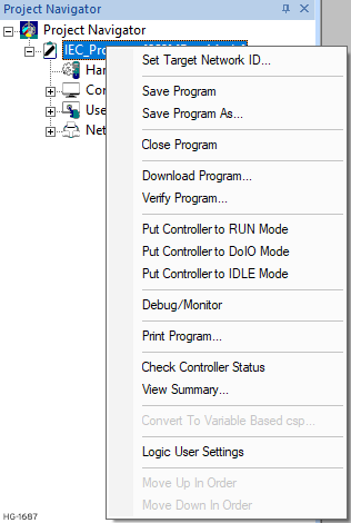
Set Target Network ID Usually refers to the ID of the device on a supported CAN, such as CsCAN, CANopen, etc. Each device must have a unique network ID. Also called Node ID.
Sets the Network ID of the Target Unit. See also: Set Target Network ID
Save and Close Program
Save Program - Saves the program
Save Program As - Saves the program as another program
Close Program - Closes the program
Download and Verify Program
See Download a Program to a Controller or Verify a Program in a Controller
Download Program - Downloads the program to the device.
Verify Program - Verifies the program with the target device.
Put Controller in Run, Idle or Do IO Mode
See also: Put Controller in Run, Stop/Idle, or Do I-O Mode
Put Controller to RUN Mode - Puts the controller in Run mode.
Put Controller to DoIO Mode - Puts the controller in DoIO mode.
Put Controller to IDLE Mode - Puts the controller in Idle mode.
Debug/Monitor Program
See also: Debugging Functions in Advanced Ladder
Logic can be monitored by clicking this option.
Print Program
Allows ladder logic to be printed out. See also Print Setup in the IEC 61131 Language Editor Programming .
Check Controller Status
Checks the controller status and displays it.
View Summary
Summary information of the program can be viewed by right-clicking this option. See below:
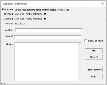
The File Name and Creation Date are displayed at the top of the box. These items cannot be edited.
-
Author: Type name or the name of the person that actually created the file (program).
-
Project: Enter the name of the project in which this file (program) belongs.
-
Notes: Any notes which the user feels is important or relevant to the file, such as the type of controller to be used, hardware limitations, or a synopsis of what the program does or how it works.
-
Show on Load: If this box is checked, then the Summary Information is displayed any time the file is loaded. If this box is unchecked, then the Summary Information is displayed only through the Right-Click on Project Name > Summary Info > Menu Selection.
Logic User Settings
Opens User Settings for IEC
Remove Program from Project
Removes the program from the project. This option is only available for programs under project
Return to the Top: Project Navigator for IEC Editors
Hardware Configuration in IEC
Hardware Configuration Overview
See also: Hardware Configuration .
Before configuring or programming a controller, the target controller model must be selected using Cscape. After selecting a controller, it is possible to determine the functions for that model are available in that specific model, and the controller can be programmed.
Note: Some controller models have built-in I/O or to have rear mounted I/O modules. When selecting these controller models in Cscape, both the controller and I/O is displayed.
Automatic Controller Configuration
Home > Hardware Configuration > Auto Config
To automatically obtain the model of target controller the PC running Cscape is connected to, press the Auto Config System button. This deletes any current settings from the configuration within Cscape, and the I/O that is fitted to the target controller displayed.

-
A Warning box appears and indicates that the settings will be deleted from the configuration within Cscape. If OK, press Yes. Then press OK.
-
If the desired controller appears as the selected controller, press OK, otherwise use Manual Controller Configuration procedure.
-
Make selections from any Network options available in the Network Ports group box
Manual Controller Configuration
Home > Hardware Configuration
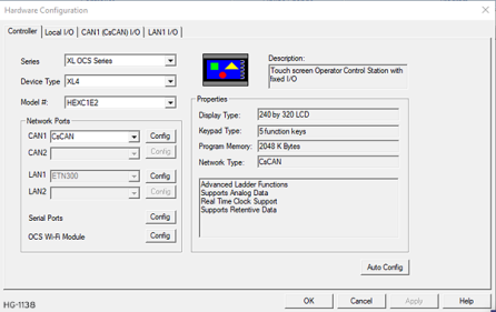
Note: Manual controller configuration does not require a connection to the target controller.
-
Select the Controller series from the Series list box.
-
Select the Device Type from the Device Type list box.
-
Select the Model # from the Model # list box.
-
Make selections from any Network options available in the Network Ports group box.
Note: I/O configurations vary greatly depending on the controller and model number selected. Be aware that the I/O may need additional configuration. For Local I/O Configuration, see General I/O Configuration.
Return to the Top: Project Navigator for IEC Editors
Control Node in IEC
Logic Modules for IEC 
See also: Logic Modules in IEC for more information on Main Loop, Subroutine, and UDFB Modules.
See also: IEC Language Editors
To better organize the application programs, the logic can be divided into multiple modules. These modules can be main loop or subroutines modules as per the requirement of the application.
-
Main Loop Modules - These blocks are executed once on each scan of the PLC in the order in which they are defined.
-
Subroutine Loop Modules - These blocks are callable from all the other block types. Subroutine modules can have private and local variables which will be allocated single storage. Hence calling the block from two different places will operate on the same private and local variables.
-
UDFB Modules - These blocks are callable from all the other block types. UDFB modules can have private and local variables which will be allocated with unique storage. Hence calling the blocks from two different places will operate on different private and local variables.
Note: UDFB Modules are only available in Variable-Based Advanced Ladder and in IEC editor programs.
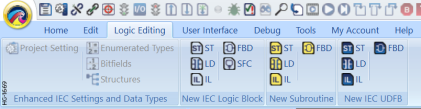
Logic Modules can be accessed two ways:
-
Option 1: Through the Menu Ribbon in the Logic Editing tab.
-
Option 2: Through the Project Navigator: Ensure the Project Navigator is open:Home > View > Project Navigator
Import Logic Module
To import a Logic Module, right-click on the Logic Modules Node and select Import Logic Module.
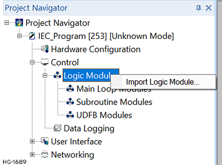
This will open a window to allow the user to select desired file.
Main Loop Right-Click Options 
Main Loop Modules for IEC 61131 Language Editors
See also:Logic Modules in IEC .
To select a new Main Loop Modules, open the Control Node in the Project Navigator > Main Loop Modules [Right-Click] > New Logic Block > IEC language. (See IEC Language Editors)
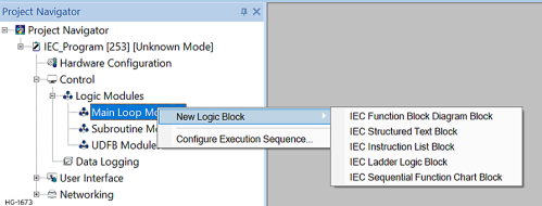
These blocks are executed once on each scan of the PLC in the order in which they are defined. The user can configure the compilation sequence of multiple blocks in main loop modules area of an IEC Program by accessing the IEC Modules Compilation Sequence Configuration dialog, see Logic Modules in IEC .
Logic Block Right-Click Options
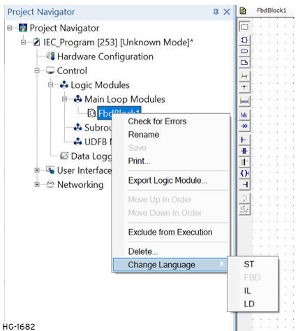
Check for Errors: Manually check a program for errors.
Rename: Allows Block to be renamed.
Save: Saves the Block
Print: Prints the Block
Export Logic Module: Exports the Block
Move Up in Order: Moves the selected module one step up the execution order.
Move Down in Order: Moves the selected module one step down the execution order.
Exclude from Compilation: Excludes the selected module from being compiled / executed during runtime.
Delete: Any Block that is not required can also be deleted from the Logic Module by right-clicking on the block and select Delete.
Change Language: Change to another IEC Language. See
Note: The same options are available for a right-click on the Subroutine Module and the UDFB Module
Data Logging in IEC 
See also: Datalogging . The Data Log utility is designed to allow any controller with a Removable Media port to periodically log register values to removable media (microSD or CompactFlash).
Return to the Top: Project Navigator for IEC Editors
The User Interface Node in IEC 
This section contains many of the functions for creating screens and working with the controller via Cscape. These functions can also be accessed through the User Interface Menu.
User Interface - Right-Click
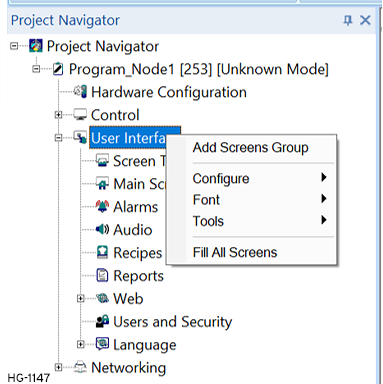
Add Screens Group
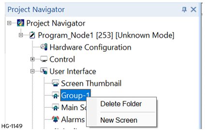
Select Add Screen Group and a new Group appears. Right-click for the options below.
Configure
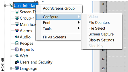
Video
Capture of a video frame is accomplished either through the optional pop-up menu associated with the video object, or through the optional video control register, which allows ladder logic control of captures. Once captured, the video frame may be displayed, saved to Removable Media, or both.
File Counters 
See also: Filename Counters .
Filename Counters is a utility for use in naming Removable Media files.
File Select 
See also: File Select .
The File Select feature allows a filename to be selected from a Removable Media Object for Canvas and stored a variable of USINT![]() Unsigned Short Integer - [Data Type USINT] - An 8-bit unsigned value. Unsigned Short Integers are used where the value of the data is expected to be in the range of 0 (zero) to 255. with an array size of 75 or 16-bit registers. This stored filename may then be used in conjunction with the Removable Media function blocks to perform operations such as reading the selected file.
Unsigned Short Integer - [Data Type USINT] - An 8-bit unsigned value. Unsigned Short Integers are used where the value of the data is expected to be in the range of 0 (zero) to 255. with an array size of 75 or 16-bit registers. This stored filename may then be used in conjunction with the Removable Media function blocks to perform operations such as reading the selected file.
Screen Capture 
See also: Screen Capture .
For controllers with screens, the Screen Capture function allows a bitmap![]() A non-compressed image file format which uses small dots in a grid pattern to create an image. or jpeg image of the displayed OCS screen to be written to the Removable Media card.
A non-compressed image file format which uses small dots in a grid pattern to create an image. or jpeg image of the displayed OCS screen to be written to the Removable Media card.
Display Settings
See also: Display Settings.
Controls the amount of time allocated to graphics after each ladder scan to ensure timely scans occur.
Slide Key 
See also: Slide Key for Canvas Series .
By sliding a finger across the display, allows a user to view a key. User can configure the key position and color.
Font 
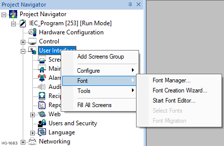
Font Manager 
See also: Fonts .
Once a font is created it must be loaded into each file where the font is desired. Fonts are added, changed or removed from a file using the Font Manager. A font is only added to the current program and is automatically downloaded to the controller when other portions of the graphics objects are downloaded.
Return to the Top: Project Navigator for IEC Editors
Tools
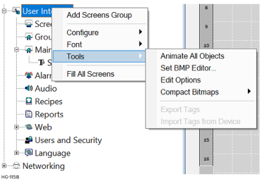
Animate All Objects 
Turns ON/OFF a constant toggle between the different conditions or states of screen objects.
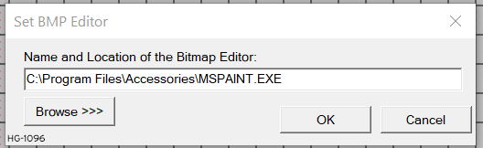
Set BMP Editor 
Specify the location of the program used to “Edit Bitmap” from within the Bitmap and Animation objects. When the following dialog opens, select Browse>>> to select file.
See also: Animated Picture/Graphic for Canvas or Picture/Graphic Object for Canvas
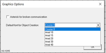
Graphic Edit Options
Edit Options - Allows for showing asterisks in Comm-linked Data Fields that are not currently active. Allows for a default font to be set for this Cscape program. Selecting Edit Options opens the Graphic Options dialog:
Compact Bitmaps - Allows for Bitmap graphics to be compressed to save graphic memory space. Option allows for just the current screen, or all screens.
Fill All Screens 
Stretches graphics to fill the entire screen on all screens.
Screen Thumbnails 
This displays thumbnails of 20 screens at a time so the screen can be picked visually instead of remembering a screen number.
See also: Screen Thumbnails
Return to the Top: Project Navigator for IEC Editors
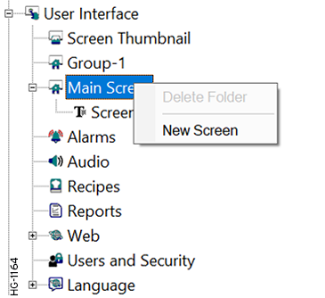
Main Screen

The user can create, move and configure graphical representations that are referred to as objects or graphic objects. New Screen - To create a new screen, right-click on Main Screen in User Interface node. Select New Screen.
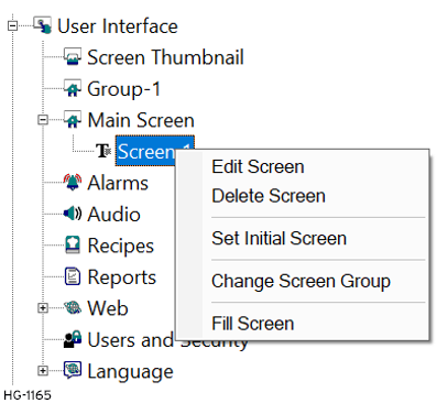
Screen Right-Click
When a user right-clicks on the Screen a menu pops up that allows the user to Edit, Delete, Set Initial, Change Screen Group, or Fill Screen.
Alarms 
See also: Alarm Configuration (Graphical) for Canvas.
Messages that are presented to the operator in response to a specific condition in the control system.
Audio 
Applications can be configured to play specific audio files based on system events, for example an alarm condition occurring, or a help request when a particular machine fault is active.
Recipe Database 
See also: Recipe Editor Configuration for Canvas .
Recipes allow the user to send or update multiple registers simultaneously.
Reports 
Allows the OCS to be configured to generate text printouts which incorporate data from the register/array elements embedded in the text.
See also: Report Editor
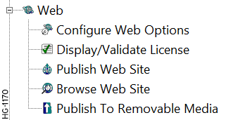
Web 
The Industrial Internet of Things (IIOT) in the industrial sectors and their applications. Cscape offers WebMI Manual and MQTT or MQTT Sparkplug .
Users and Security 
Using this feature, graphics objects can be password protected. This opens the User AccessLevel Editor.
See also: Level Based Security
Language 
For more details about Language see Multi-Language Support .
Return to the Top: Project Navigator for IEC Editors
Export and Import Strings

See also: Multi-Language Support .
Export Strings - To copy the phrases from the file onto the clipboard that is in a TAB delimited format that is compatible with Microsoft Excel.
Import Strings - To setup a table for phrase translation that can be downloaded.
Language Options 
This includes Language Options and Right to Left Languages.
See also: Multi-Language Support .
Display Language 
Allows display any of the 24 sets of phrases loaded.
See also: Multi-Language Support .
Return to the Top: Project Navigator for IEC Editors
The Networking Node in IEC
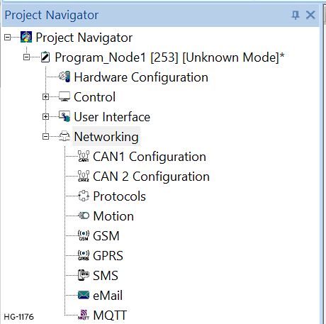
Network Configuration 
Network Configuration - This opens the Network I/O Configuration dialog for this controller. See also: CAN Communications
Network Configuration (CAN2) - This allows user to configure CAN2 or CsCAN. See also: CAN Communications
Protocols 
Through loadable protocol device drivers, certain models of the OCS family can provide the ability to exchange data with remote devices.
See also: Protocol Configuration
GSM 
A network used for connecting two devices and exchanging data. It can be used by OCS with internal GSM modem to communicate to another device connecting to Internet/ GSM/ PSTN network.
See also: GSM Configuration
GPRS 
Network can be used to establish communication between OCS and any other communicating devices having unique IP address and port configuration.
See also: GPRS (General Packet Radio Service)
SMS 
(Short Message Service) A type of communications process that enables the transmission of short text messages/data transfers to and from mobile devices such as cell phones.
See also: SMS Configuration
Email 
This feature is designed to send email messages embedding real time data of the controllers and can be configured using Cscape.
See also: Email Configuration
MQTT 
A simple messaging protocol. It is a lightweight publish and subscribe system where user can publish and receive messages as a client.
See also: MQTT or MQTT Sparkplug
Return to the Top: Project Navigator for IEC Editors